

- BY nwmcadmin
- POSTED IN Product Development
- WITH 1 COMMENTS
- PERMALINK
- STANDARD POST TYPE
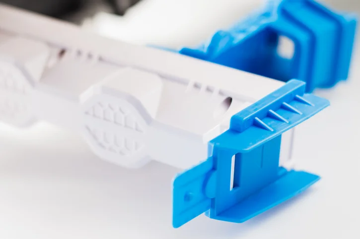
Gates and parting lines are two of the most important design considerations in injection molding. Although they are often overlooked during the early stages of product development, both have a direct impact on part quality, cosmetic appearance, manufacturability, and tooling costs.
Every injection molded part requires a gate to allow molten plastic to enter the mold cavity, and every mold has at least one parting line where the two halves of the mold separate. Careful planning of these features helps produce stronger, more consistent parts while minimizing cosmetic defects and reducing manufacturing challenges.
Understanding how gates and parting lines work can help designers create parts that are easier and more economical to manufacture.
What are injection molding gates?
Each plastic part design must have a gate, or an opening that allows the molten plastic to be injected into the cavity of the mold. Once the cavity is filled, the gate freezes and is separated from the finished part during the molding process.
Although the gate itself is relatively small, its design has a significant impact on the finished part. Gate type, design, and location can affect part packing, gate removal or vestige, cosmetic appearance, cycle time, shrinkage, warpage, and overall part quality.
There are several styles of gates commonly used in injection molding, and each offers advantages depending on the part geometry, material, and production requirements.
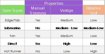
Common Types of Injection Molding Gates
Several gate styles are used throughout the injection molding industry. Selecting the proper gate depends on the size of the part, the resin being molded, cosmetic requirements, and the desired manufacturing process.
Edge Gates
Edge gates are one of the most common gate styles. Located along the edge of the part, they are simple to manufacture, easy to modify, and work well for a wide variety of applications.
Pin Gates
Pin gates are frequently used with hot runner systems and multi-cavity molds. Because they leave only a small gate vestige, they are often selected for parts where appearance is important.
Fan Gates
Fan gates gradually widen before entering the cavity, allowing plastic to spread over a larger area. They are commonly used for larger or thinner parts where even material flow helps reduce internal stresses and improve surface finish.
Submarine (Sub) Gates
Submarine gates enter the part below the parting line and automatically separate from the part during ejection. They reduce secondary trimming operations and are commonly used in high-volume production.
Specialized gate styles, such as diaphragm and tab gates, may also be used for certain applications where unique flow characteristics or stress reduction are required.
Why does gate location matter?
Choosing the correct gate location is just as important as selecting the gate style. The location determines how molten plastic fills the mold, where pressure is applied, and how the material cools inside the cavity.
A well-positioned gate helps ensure complete filling, consistent packing, and predictable shrinkage. A poorly positioned gate can lead to cosmetic defects, weld lines, trapped air, excessive warpage, or incomplete filling.
Part Strength
Plastic should generally enter the mold through the heaviest cross section whenever possible. This allows the material to properly pack thicker areas before the gate freezes, helping minimize voids and improving the structural integrity of the finished part.
Cosmetic Appearance
Because every gate leaves a small vestige after it is removed, gate location also affects the appearance of the finished product. Designers often position gates on hidden surfaces or non-cosmetic areas whenever possible to minimize visible gate marks, flow lines, or blush marks.
Shrinkage and Warpage
As plastic cools, it naturally shrinks. Proper gate placement helps maintain packing pressure throughout the part, reducing uneven shrinkage that can lead to warpage or dimensional variation. You can read more about this phenomenon in our more in-depth blog post here.
Mold Performance
An efficient gate location can shorten flow paths, improve filling, reduce injection pressure, and contribute to faster, more consistent production cycles. These improvements help increase manufacturing efficiency while maintaining part quality.
Best Practices for Choosing Gate Locations
To avoid problems in plastic part design resulting from gate location, the following guidelines are commonly used:
- Place gates at the heaviest cross section to improve part packing while minimizing voids and sink marks.
- Position the gate where manual or automatic de-gating can be performed efficiently.
- Minimize flow path length to reduce cosmetic flow marks and improve filling.
- Consider multiple gates for larger or more complex parts when necessary to achieve balanced filling.
- For thin-walled parts, evaluate adding flow channels or adjusting wall thickness if filling problems occur.
- Whenever possible, avoid placing gates on highly visible cosmetic surfaces or critical sealing areas.
Every part presents its own unique design challenges. Rex Plastics analyzes each part individually and recommends the best gate design based on the product requirements. If gate appearance is critical, Rex Plastics will propose the optimum gate location for customer approval.
Should customers specify gate locations?
In many cases, customers know which surfaces of a part will remain visible after assembly or which features require the highest cosmetic quality. Sharing this information with your injection molding partner is extremely valuable during the design process.
However, the exact gate location is typically determined by the mold designer. They must balance cosmetic requirements with material flow, packing pressure, cooling, shrinkage, mold complexity, and manufacturing efficiency to achieve the best overall result.
By working together early in the design process, product designers and mold engineers can often avoid costly tooling changes while producing higher-quality parts.
What is a parting line in injection molding?
A parting line is the line of separation on the plastic part where the two halves of the injection mold meet. The line actually represents the parting plane that passes through the part. In simple part designs this plane may be a flat surface, but it is often a complex shape that follows the perimeter of the finished part and its various features.
Every injection molded part has at least one parting line because every mold must open to release the finished component. While parting lines cannot be eliminated, thoughtful mold design can help place them where they have the least impact on function and appearance.
Parting lines can also occur anywhere two pieces of a mold meet. This includes side actions, tool inserts, shutoffs, and other tooling components.
Why are parting lines important?
The location of the parting line affects much more than the appearance of the finished part. It can influence mold complexity, manufacturing cost, flash formation, draft requirements, and even how easily a part can be ejected from the mold.
Whenever possible, designers try to position the parting line where it is less noticeable or where any small amount of flash can be easily removed without affecting the function of the part.
Early consideration of the parting line can often simplify tooling and improve manufacturability.
How do parting lines affect plastic flow?
Keep in mind that the plastic melt naturally flows toward the parting line because it is often the easiest place for displaced air to escape through mold vents.
Proper venting along the parting line helps prevent trapped air, burn marks, short shots, and other molding defects. Because gate location and venting work together, mold designers often evaluate both features simultaneously when designing the mold.
This is one reason why gate placement and parting line location are closely connected during mold development. Read our in-depth blog on venting here for more information.
Common Types of Parting Lines
Parting lines generally fall into two broad categories: straight (flat) and stepped (curved).
Straight (Flat) Parting Lines
Straight or flat parting lines are typically found on simpler parts. They are easier to machine and often reduce tooling complexity and manufacturing costs.
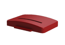
Straight/Flat
Stepped (curved) parting lines
Stepped or curved parting lines follow the contours of more complex part geometries. While they require more sophisticated tooling, they allow designers to mold parts with more intricate shapes while maintaining proper draft and manufacturability.
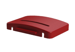
Stepped/Curved
What are mouse holes in injection molding?
Mouse holes can be an excellent way to create a cut-out in the side of a part without requiring a side action. Eliminating side actions can simplify mold construction, reduce tooling costs, and improve long-term reliability.
Below is a typical example of a mouse hole.
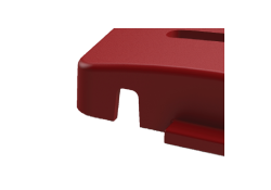
When designing a mouse hole, be sure there is ample draft on the side walls. In order for the mold surfaces to seal properly, a minimum draft angle of 3° is generally recommended to improve tool life and reduce wear.
How To Design Plastic Parts with Better Parting Lines
When designing injection molded parts, consider the parting line early in the product development process. Simple adjustments to geometry can often improve manufacturability while reducing tooling costs.
Some general recommendations include:
- Add adequate draft to surfaces that cross the parting line.
- Avoid unnecessary undercuts whenever possible.
- Position the parting line away from highly visible cosmetic surfaces when practical.
- Consider how flash would be removed if it occurs.
- Collaborate with your injection molding partner before finalizing the part design.
These considerations can help produce parts that are easier to manufacture while improving consistency and overall quality.
Learn More
Interested in developing a plastic product? Rex Plastics provides support throughout the product development process, from design for manufacturability and prototyping to mold design and production injection molding. Contact our team to learn more about our prototyping and 3D printing services and how we can help optimize your next plastic part.
Frequently Asked Questions
| Question | Answer |
|---|---|
Can gate location affect the appearance of weld lines on an injection molded part? |
Yes. Weld lines form when two separate flows of molten plastic meet inside the mold cavity. The location of the gate influences where these flows travel and where they eventually join. By strategically placing the gate, mold designers can often move weld lines away from highly stressed or visible areas and improve the overall appearance and strength of the finished part. |
Can a part have more than one parting line? |
Yes. While every injection molded part has at least one primary parting line, complex molds may include additional parting lines created by inserts, slides, lifters, or other tooling components. These secondary parting lines allow manufacturers to create more complex geometries while still enabling the part to be released from the mold. |
How early should gate and parting line decisions be made during product development? |
Gate and parting line considerations should be evaluated during the initial design phase, before the mold is built. Making changes after tooling begins can be costly and time-consuming. Early collaboration between product designers and injection molding engineers helps identify potential issues, optimize part geometry, and create a more efficient manufacturing process. |
Read the other parts of this series:
- Fundamentals of Plastic Part Design – Part 1: Injection Molding
- Fundamentals of Plastic Part Design – Part 2: Draft
- Fundamentals of Plastic Part Design – Part 3: Sink and Warp
- Fundamentals of Plastic Part Design – Part 4: Ribs and Bosses
Referencing content from this page?
Please attribute either https://rexplastics.com/ or https://rexplastics.com/product-development/fundamentals-plastic-part-design-part-5-gates-parting-lines/
Suggested Citation:
Rex Plastics. (2016, July 20). Gates and Parting Lines: Fundamentals of Plastic Design Part 5. https://rexplastics.com/product-development/fundamentals-plastic-part-design-part-5-gates-parting-lines/

The blog “Fundamentals of Plastic Part Design – Part 5: Gates and Parting Lines” offers a well-rounded explanation of two essential elements in plastic molding. The detailed discussion of gate types and parting line considerations is especially useful for optimizing mold design and achieving high-quality parts. This content is highly beneficial for both designers and engineers seeking to improve production outcomes. Thank you for this informative post, and I look forward to more technical insights that enhance understanding of the plastic molding process!